IT USA (Imdex): PCB Test Fixture
Bench-tested prototype
Cut estimated PCB check time from 8 min (timed, by hand) to 1.5 min per board. Designed and built a bed-of-nails fixture that probes all 12 test points in one clamp press and logs readings straight to Excel. Not yet reproduced for the production line.
Blurred under NDA.
My role.Designed, built, and tested the mechanics, electronics, and logging code.
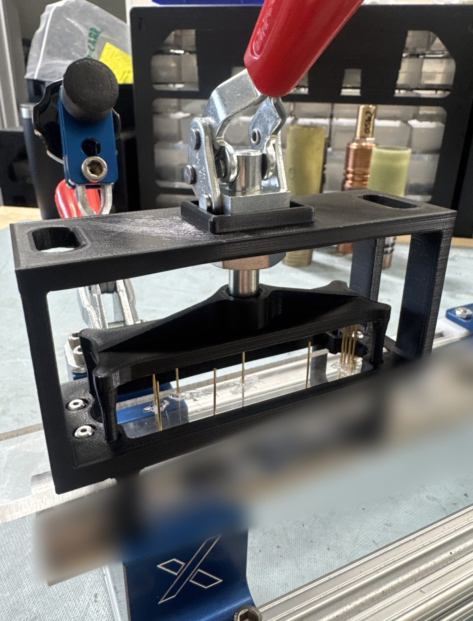
Problem
Voltages on each OMNIx downhole gyro survey tool board were checked by hand with a meter probe and typed into a spreadsheet. I timed it at 8 min per board.
Design rationale: several boards share one mounting-hole pattern, so the carrier locates off those holes and one fixture serves them all. Only the probe cartridge changes for each board and test location. Boards come back from the field inside the tool, so the fixture bolts to existing threaded holes in the chassis and tests the board in place.
Constraints: 12 test points less than 0.040 in apart; readings logged to the team's existing Excel sheet.
Design
1Toggle clamp
One clamp press seats a probe on all 12 test points.
2Probe carrier
3D-printed carrier locates off the board's mounting holes, rides linear rails, and lands a spring-loaded probe on every test point.
3Microcontroller
An STM32 reads the three converters; my C++ program logs time-stamped readings to the team's Excel sheet.
4Converters
A voltage divider and noise filter on each channel feed three 16-bit analog-to-digital converters (ADS1115).
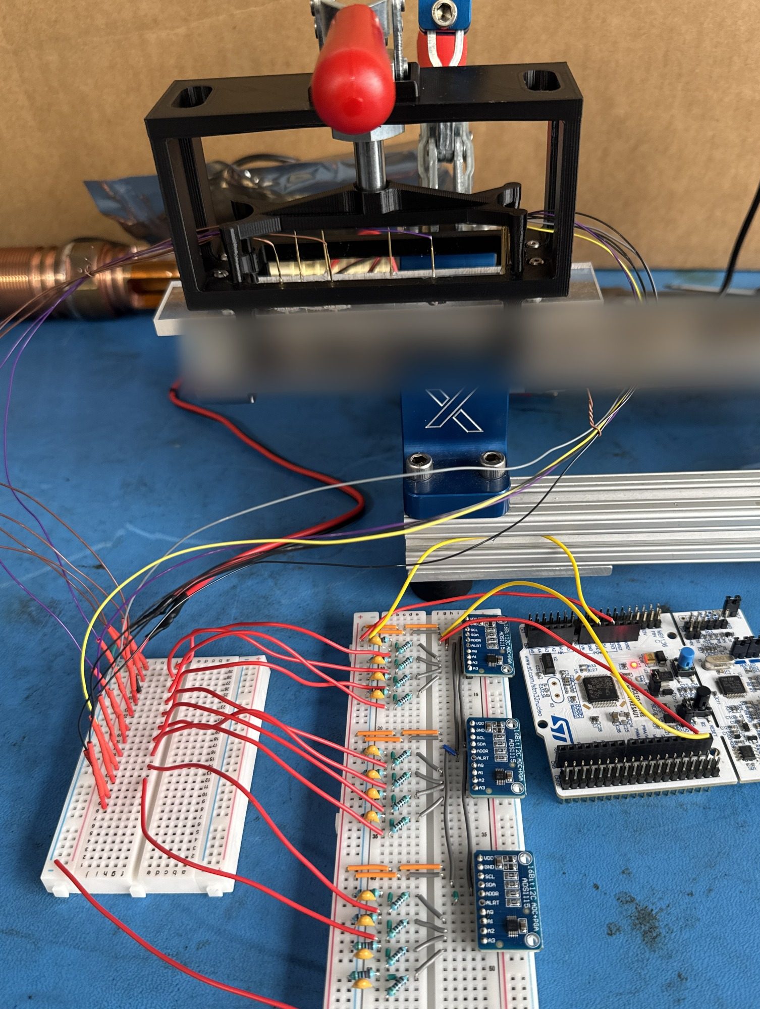 1Toggle clamp2Probe carrier3Microcontroller4Converters
Validation
Build sequence: a first article (two clips, one converter, one channel), then the printed carrier with spring probes, the clamp, and the guide shaft.
Ran 20 prototype trials against calibrated multimeters. Readings averaged 0.0003 V off the meters before a fixed offset correction in the code, and 0.0000 V ± 0.0001 V after it. Prototype steps totaled about 65 s: 30 s to bolt in, 5 s to read, 30 s to unbolt. The 1.5 min estimate adds handling time to those steps.
Failure mode: 1 of 20 trials missed a probe, traced to slider bushing tolerance. Tighter bushings are the next change.
ToolsSolidWorks, 3D printing, STM32, ADS1115 16-bit ADC, C++, Excel, Data acquisition