Atlas Copco: Sensor Calibration Fixture
In development
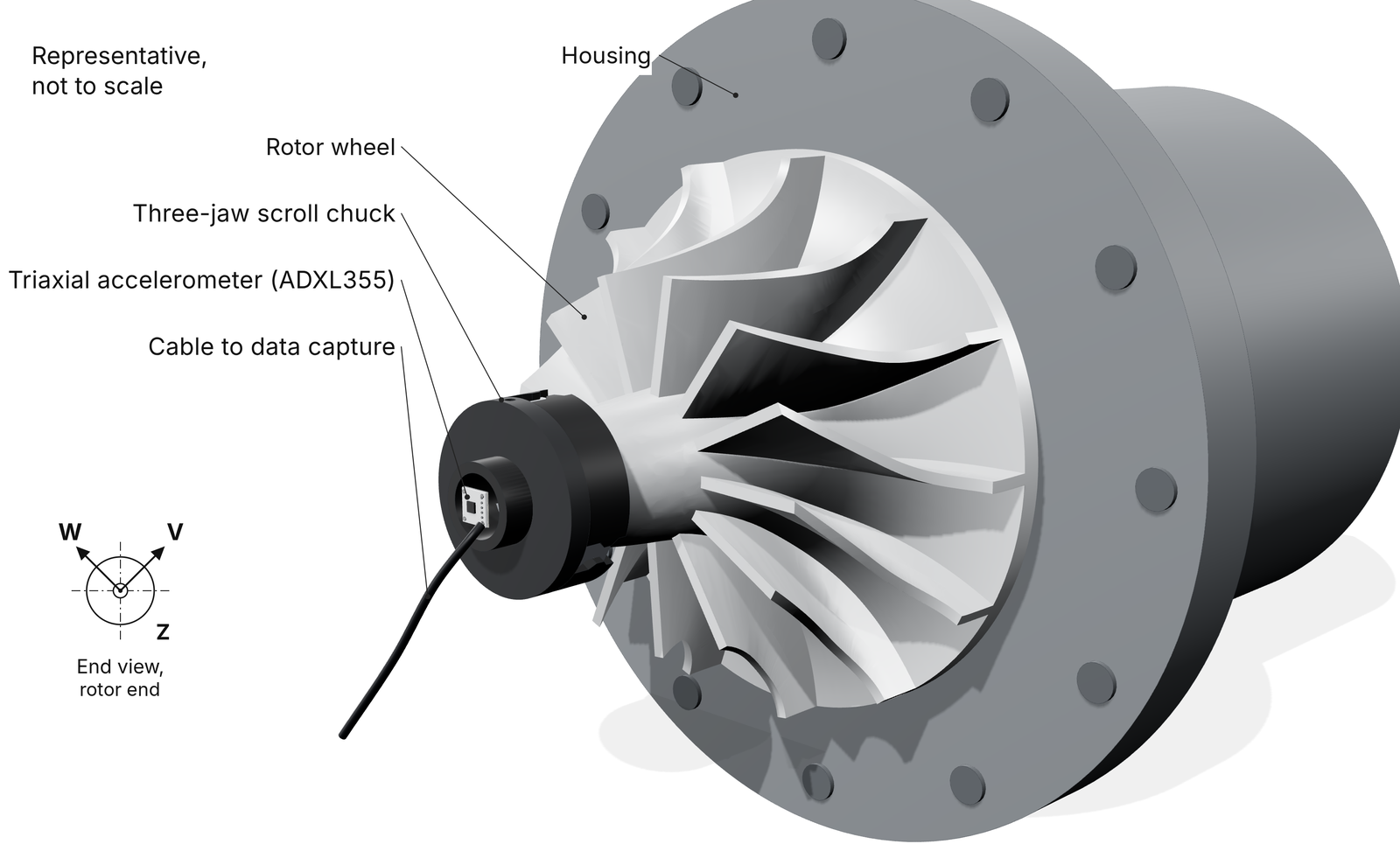
Modeled a 2.25 µin (0.057 µm) uncertainty bound against a 39 µin (1 µm) target. Developing a fixture that calibrates the magnetic-bearing position sensors on Atlas Copco turboexpanders from measured rotor motion, in place of dial indicators. An accelerometer on a chuck at the rotor nose records the motion.
My role.Signal processing and electrical lead on a team of 4, responsible for the measurement method, embedded readout, fit code, and uncertainty budget.
Problem
The sponsor calibrates the position sensors on its rotating machines with dial indicators: half a day to a full day for setup, calibration, and teardown.
Contributions
- Wrote the embedded C++ that reads the accelerometer, indexes each sample, and sends the data to the laptop
- Wrote the Python sine fit that turns the data into rotor displacement
- 3D-printed a demonstration rotor for design reviews
- Built a 9-source uncertainty budget for the ADXL355 with the GUM method (Guide to the Expression of Uncertainty in Measurement) and checked it with 400,000 Monte Carlo runs
Measurement method
Design rationale: during calibration the bearing controller moves the rotor sinusoidally at a commanded frequency, so its acceleration is a sine at that known frequency. Displacement follows directly: X = a / ω², with ω = 2πf. Fitting a sine and cosine at that one frequency, plus a constant offset and a slow drift term, rejects noise at other frequencies and the gravity offset. It avoids double-integrating a drifting signal. The signal is small: 0.001 in (25 µm) of motion at 10 Hz is about 10.1 mg of acceleration.

Uncertainty analysis
Each bound is two standard deviations of nine modeled error sources plus their biases. Nothing has been measured yet.
Next steps: Shake-table test of the accelerometer to replace the model with measured data.
ToolsPython, C++, ADXL355 accelerometer, GUM uncertainty budget, Monte Carlo simulation, 3D printing