Lightweight Bracket for Metal 3D Printing
Simulation
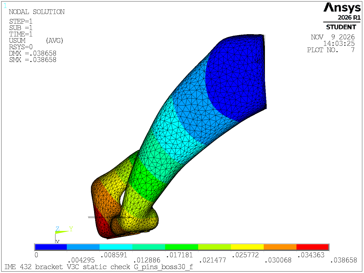
Cut modeled mass 35.6% (30% required) on a 316L bracket redesigned for metal 3D printing. Deflection is modeled against the wall restraint.
My role.Ran the design and analysis in Fusion 360 and Ansys.
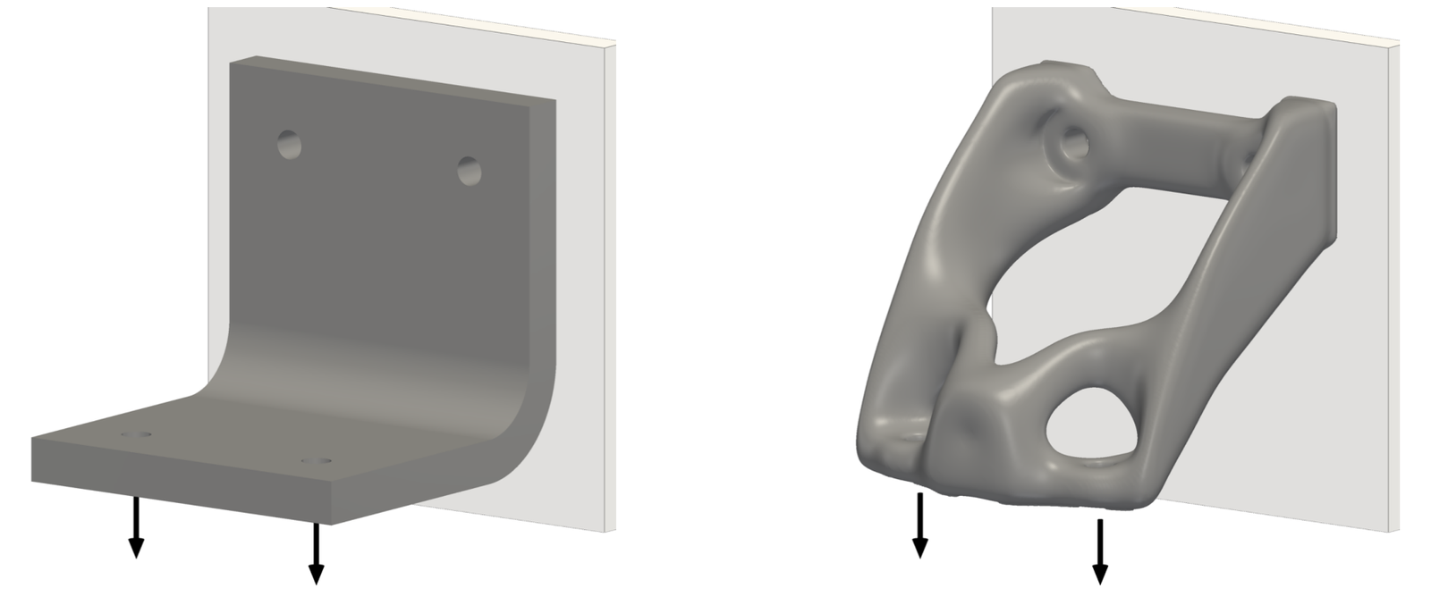
Problem
Redesign an aerospace bracket for laser powder bed fusion (LPBF) in 316L stainless steel.
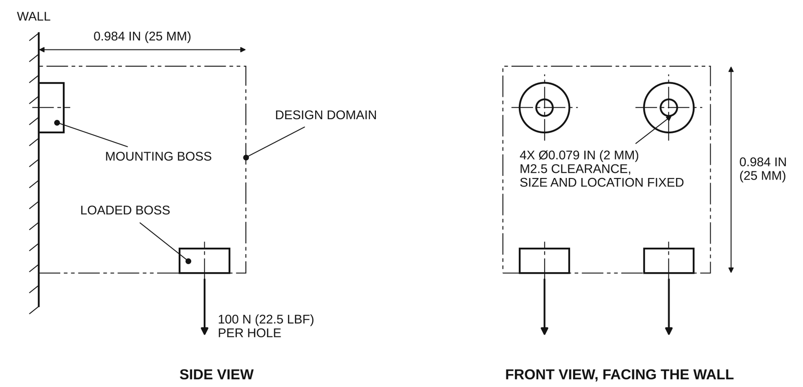
Constraints: four holes fixed in size and location; 22.5 lbf (100 N) on each loaded hole; at least 30% lighter; tip deflection under 0.0020 in (0.05 mm).
Contributions
- Ran Fusion 360 generative design, holding body stress under the limit and limiting overhangs that need supports (45° rule)
- Smoothed the result into a printable surface; defined holes and machined faces in CAD
- Checked it with finite element analysis (FEA), then rebuilt the model and mesh in Ansys to confirm the result
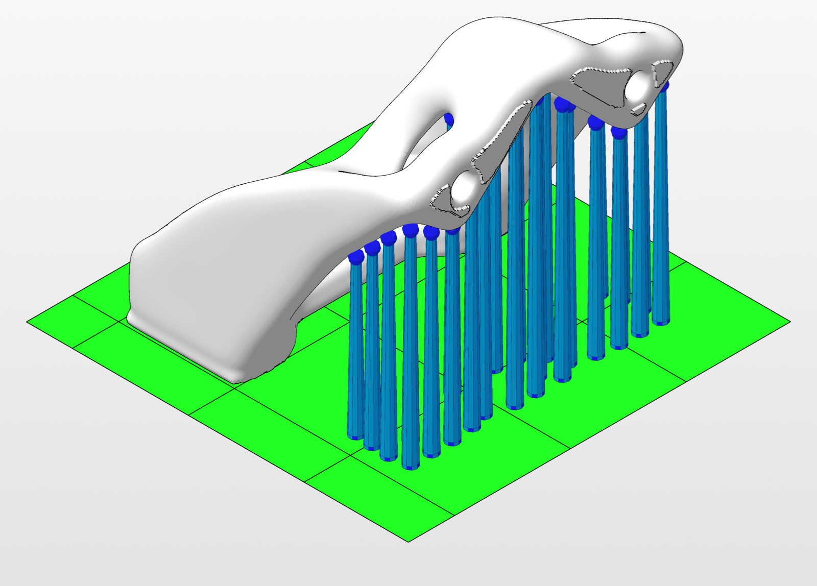
- Compared six build directions; chose the one needing the least support
Analysis
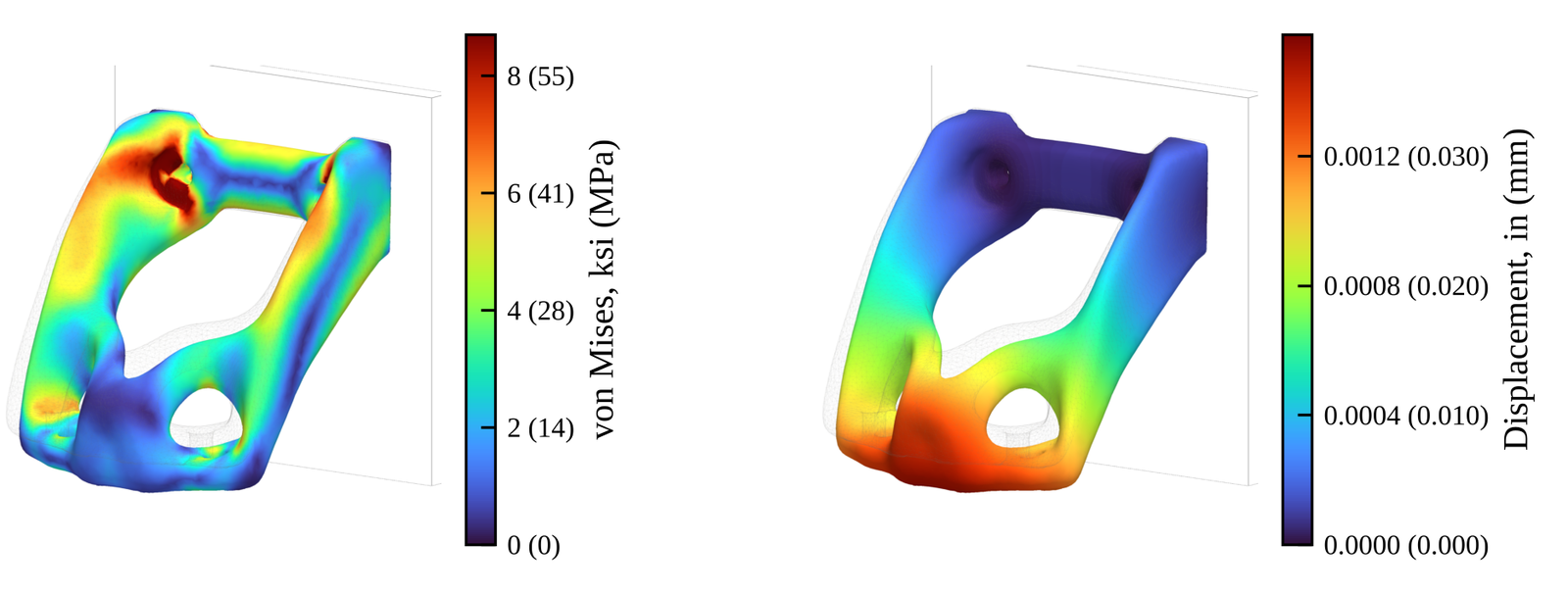
Body stress 7.8 ksi (54 MPa) against the 24.7 ksi (170 MPa) limit.
Design comparison
| Item | Shape optimization | Generative design |
|---|---|---|
| Mass reduction | 32% | 35.6% |
| Factor of safety | 2.47 | 3.2 |
| Max stress, ksi (MPa) | 10.1 (69.8) | 7.8 (53.5) |
| Max deflection, in (mm) | 0.00154 (0.039) | 0.00150 (0.038) |
| Print difficulty | Low: 0.31 in (7.8 mm) tall, flat, little support | Medium: 0.98 in (25 mm) tall, 0.13 in² (84 mm²) supported |
| Post-processing | High: 5 machined faces plus holes | Medium: 2 faces plus holes, rest bead blasted |
Generative design was recommended: similar mass and deflection, 23% lower stress, and fewer machined faces. Shape optimization stays as the backup, with a shorter, faster print.
Print orientation
| Build direction | Support volume, in³ (cm³) | Supported area, in² (mm²) |
|---|---|---|
| −Y, wall face down (chosen) | 0.073 (1.20) | 0.130 (84) |
| −X | 0.085 (1.40) | 0.251 (162) |
| +X, boss faces down | 0.109 (1.79) | 0.267 (172) |
| −Z | 0.137 (2.25) | 0.290 (187) |
| +Z | 0.138 (2.26) | 0.291 (188) |
| +Y, wall face up | 0.168 (2.76) | 0.401 (259) |
The wall face (Datum A) goes on the plate and is machined afterward, so plate scars never touch the finished datum.
Post-processing
- Stress relieve on the build plate.
- Wire EDM off the plate, remove supports, blend scars.
- Machine the wall face flat (Datum A); drill and ream the two mounting holes, Ø0.079 in (2.0 mm).
- Flip; machine the loaded boss faces (Datum B); drill and ream the two loaded holes.
- Bead blast the organic surfaces; break edges 0.008 in (0.2 mm) max.
- Inspect: scan against CAD (Keyence), Ra on machined faces.
Mounting cases
Wall face held
0.00099 in (0.0252 mm) tip deflection, 1.99 times under the 0.0020 in (0.05 mm) limit. Pass.
The whole wall face is held fixed. Body stress is 6.8 ksi (46.6 MPa) against the 24.7 ksi (170 MPa) limit. The original bracket deflects 0.00360 in (0.0915 mm) in the same case and fails. No contour plot was saved for this case.
Contact patches
0.00136 to 0.00173 in (0.0346 to 0.0439 mm), depending on patch size. Pass in every size run.
| Wall support | Deflection, in (mm) | Limit ÷ deflection | Check |
|---|---|---|---|
| Ø0.197 in (5 mm) patch per hole | 0.00173 (0.0439) | 1.14 | Pass |
| Ø0.236 in (6 mm) patch per hole | 0.00152 (0.0387) | 1.29 | Pass |
| Ø0.276 in (7 mm) patch per hole | 0.00136 (0.0346) | 1.45 | Pass |
| Washer ring under each screw head, wall in compression only | 0.00121 (0.0306) | 1.63 | Pass |
The course analysis does not state its patch size. The Ø0.236 in (6 mm) patch matches its 0.00150 in (0.0381 mm) within 2.6%. With that analysis's contact, the original bracket deflects 0.00716 in (0.1818 mm) and fails.
No wall contact
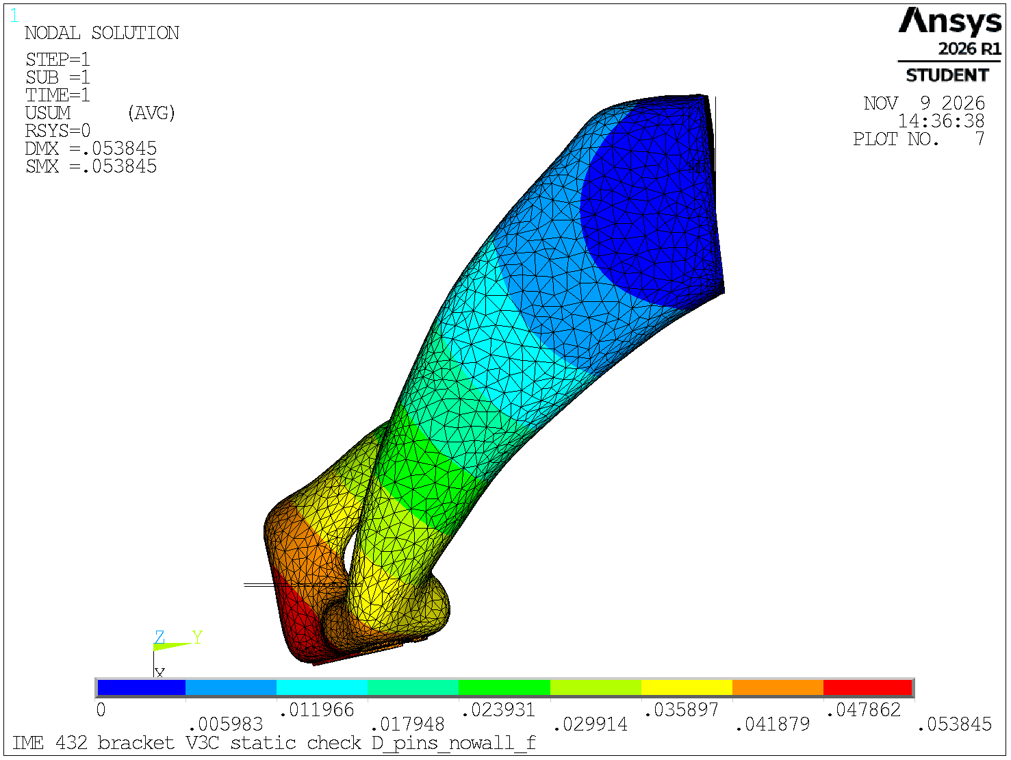
0.00212 in (0.0538 mm), 8% over the 0.0020 in (0.05 mm) limit. Fail.
With no wall contact, only the pins in the mounting holes carry the load. A washer ring under each screw head, with no wall, is over at 0.00203 in (0.0515 mm). Mesh refinement does not rescue it: the result moves 0.04% between the medium and fine meshes. The original bracket deflects 0.00764 in (0.1941 mm) in this case.
Mesh convergence
| Mesh | Nodes | Deflection, in (mm) | Body stress, ksi (MPa) | Wall-edge peak, ksi (MPa) |
|---|---|---|---|---|
| Coarse | 18,592 | 0.00099 (0.0253) | 6.4 (44.0) | 14.0 (97) |
| Refined bores | 82,876 | 0.00099 (0.0253) | 6.8 (46.6) | 15.9 (110) |
| Medium | 92,847 | 0.00099 (0.0252) | 6.8 (46.6) | 17.7 (122) |
| Fine | 116,515 | 0.00099 (0.0252) | 6.8 (46.6) | 19.7 (136) |
Deflection moves 0.3% across the four meshes. The wall-edge peak rises with every refinement, the sign of a contact-edge singularity with no converged value, so it is not quoted as a margin. The pinned mounting bores in the course analysis behave the same way.
Limitations
The design relies on the bracket sitting flat on a stiff wall; without wall contact, modeled deflection is 8% over the limit. Stresses at the mounting holes, the wall edge, and the bolted joint are not yet resolved.
Next steps: Model the bolted joint at the mounting holes, then a full-size plastic proof print.
ToolsFusion 360 generative design, FEA, Ansys, Design for LPBF (316L), Support and orientation planning